I recently started playing with ESP8266 and really like it. So I decided to make a simple OpenSenseMap temperature and pressure ( and humidity with BME280 ) stand-alone device. The idea was to have it run off battery for a long period of time and if needed, to charge it via solar panel(s).
I decided to go with ESP-12S, which is bare-bone ESP and does not have usb input or any other schematics like Wemos D1 or similar. That’s the cheapest option available on E-Bay, AliExpress and similar sites. However, the main reason why I decided to go with it is, because I wanted to add it to a printed circuit board.

When I started playing, I had no appropriate way to program it, so I made myself a “programmer” for my ESPs :). Very rough, but it works. I used schematics from this Instructable.
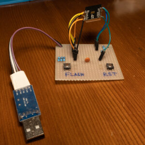
Here is how my first prototype version looks like ( worked for few weeks without problems so far):

Unfortunately I don’t have the schematics for it, but the attached one is pretty similar – it has one CLR button more, which is used when resetting device – if held while resetting, the device won’t go to deep sleep, but run a web server instead. If you hold it, press reset and keep CLR for 5 to 10 seconds pressed, the wi-fi configuration will be wiped and a Soft AP will be started. If you keep it for 10+ seconds pressed, the entire configuration will be cleared up.
Here is the schematic I’ve made, which works pretty well:

I’ve used the following parts:
- ESP-12F or ESP-12S. Bought it from AliExpress.
- 10kOhm resistor for pull-up ( 6 x )
- Omron switch B3F-1000
- MA04-1 4 pin header. Had some lying around, so I reused them. You can use any kind of connector here, it’s for programming only.

- MicroUSB battery charger with protection TP4056. Bought it from AliExpress.
- BME280 ( or BMP180 – the pinout is similar. BMP180 is cheaper, but does not support humidity )
- 100n capacitor between Vcc and GND.
- Terminal blocks (with screws) for power (battery) and solar – AK500/2-H – pretty standard and can be found anywhere. I bought it from local electronics store. You can use any, but the important thing is that the pitch is 5.0 mm. My variant is DG301-5.0-02P ( two pin version ).
Ultimately, I’ve made also a PCB with the free version of Eagle ( as it fit perfectly into the limits ).
Here is the zip file with schematics, pcb and the custom library for the power connector ( I just made it show + and – instead of 1 and 2 ) – ESP12S-measure-v1
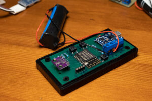
And here is how it looks ready with parts assembled:
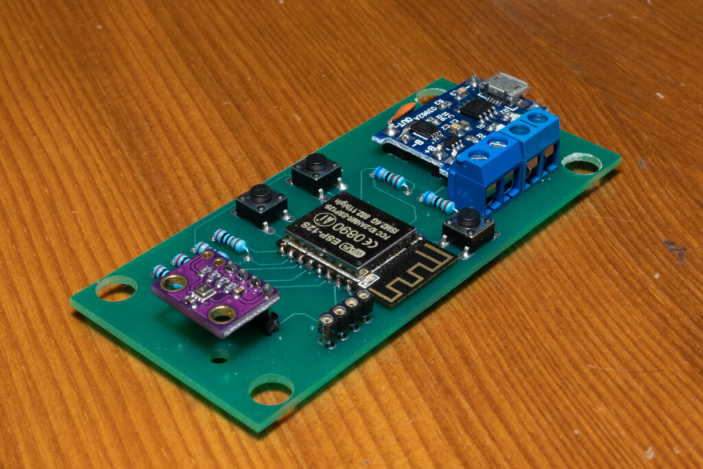
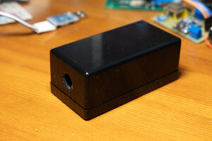
I’ve fitted it into a black enclosure ( cutouts match it perfectly ). The enclosure’s specifications are here. I bought it from here, but should be possible to find it anywhere.
According to the schematics, CLR is connected to GPIO4 (pin 6). However, I think there’s a mistake in the Eagle part for ESP-12, and CLR is actually connected to GPIO5 (pin 5). That’s not a problem at all, as it’s easily configured in software.
Another minor thing is that SCL and SDA seems to be inverted as it did not initially discover the BME280. However, I’m too lazy to look into that and simply switched it like this:
Wire.begin(2, 0);
Lazy, I know 🙂 But it works and I don’t bother anymore.
Here is a Gitlab link with complete source. Have in mind, that I can update it so it might not work properly always, but I’ll try to keep it working.
For uploading the code, I’m using Atom + PlatformIO, as it fits best.
Press FLASH button and then press Upload button. When “Uploading …” appears, press and release the RESET button. Then you can depress FLASH.
For connection, you can use any USB-to-Serial dongle, just make sure you have the right drivers and it’s discoverable. You can check this post for more details.
Remember to upload also the SPIFFS file system. You can do it when you open terminal window in Atom:
![]()
and type:
pio run --target uploadfs
Of course, you need to be in Flash mode ( check above ) in order to upload it.
Once the schematic + SPIFFS data are uploaded, you can press RESET and monitor the serial output:
![]()
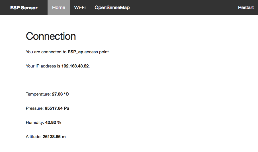
Initially, a Soft Access Point will be created ( ESP_ap ) without password. Connect to it and then open http://192.168.4.1 in your browser to configure it.
You will see a page like this. There are some (small) bugs, but I’ll sort them out.
Configure the SSID from this page and connect to it. Actually it just saves it.
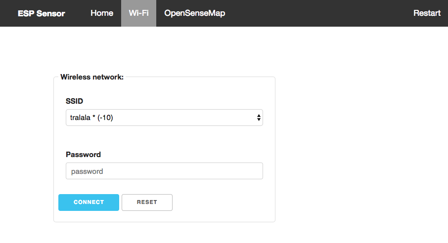
Go to next page – OpenSenseMap and configure your sensor ids:
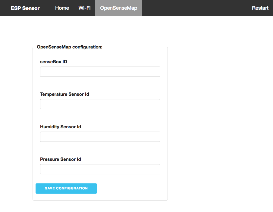
You need to go to OpenSenseMap and register new SenseBox. You can then add Temperature, Humidity, Pressure – whichever you need to monitor. Note their IDs and fill them here. Press “Save configuration”.
Now you can Restart the ESP via the top right menu or with RST button.
If you missed the OpenSenseMap configuration or made some mistakes, using CLR button you can do several things:
- Start web server, no deep sleep mode:Press CLR button, press and release FLASH, hold CLR for about 2 seconds, then release it.
- Reset Wi-Fi hotspot configuration ( will default to SoftAP ESP_ap without password ):Press CLR button, press and release FLASH, hold CLR for about 5-6 seconds, then release it. ESP will self-reset afterwards.
- Reset everything:Press CLR button, press and release FLASH, hold CLR for about 10-15 seconds, then release it. ESP will self-reset afterwards.
Check initially in the console and you should be able to see something like this:
Sensor Station 0.0.2 (kkazakov@gmail.com)
Recovered credentials:
wifiAPName
********
Recovered OSM settings:
5xxxxxxxxxxxxxxxxxxxxxx1
5xxxxxxxxxxxxxxxxxxxxxx2
5xxxxxxxxxxxxxxxxxxxxxx3
5xxxxxxxxxxxxxxxxxxxxxx4
Connect requested
Connecting as wifi client...
connRes: 3
Status: 3


Connected to wifiAPName
IP address: 192.168.88.21
T=25.30 *C, P=95495.73 Pa, H=45.35 %, A=26139.45 m
BME sensor reading, posting to OpenSenseMap ...
 done.
Going into deep sleep
Then you should be able to see your readings on your box’s opensensemap address ( e.g. for mine: https://opensensemap.org/explore/5b006b6d223bd80019002e02)
Note; I haven’t yet tested how much it lasts with the battery, but I will do so. My prototype station lasts 3 weeks so far without showing any sign of stopping, but it’s powered by 2 x 6000 MAh 18650 batteries ( which is plenty ).
However, if you power it by smaller battery, it may last few months instead of 1-2 years. I’m yet to properly calculate that 🙂
The box:

I made a hole near the temperature sensor:
And then inside it barely fits with the battery, but it does 🙂
I hope you enjoyed it. As always – I might missed something, you can ask in the comments if there’s something unclear.
1 comments On Measuring temperature, humidity, pressure with ESP8266, BMP180/BME280 on a rechargeable battery
wasp, thanks a lot for the article post.Much thanks again. Fantastic.